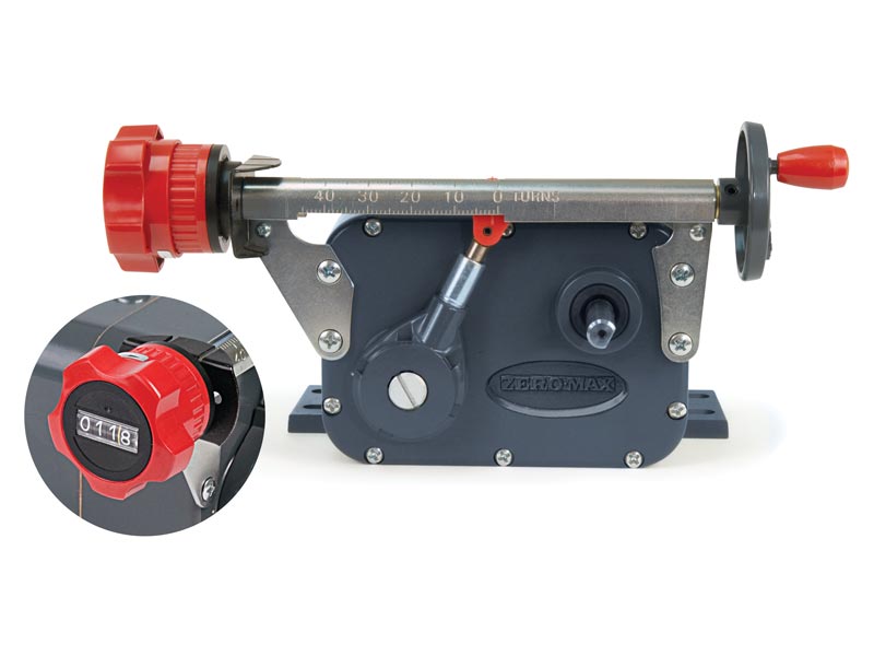
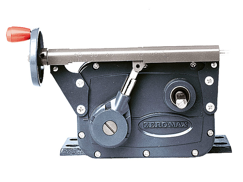
Mechanical gearbox for speed control
Simple and accurate
1,36 Nm – 22,6 Nm
1,36 Nm – 2,8 Nm
Up to 22,6 Nm
What is a variable speed drive and how does it work?
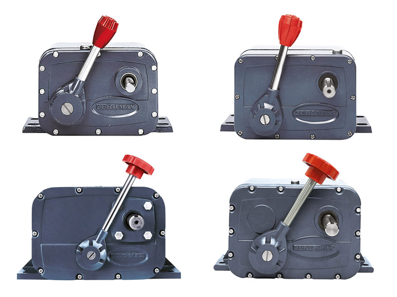
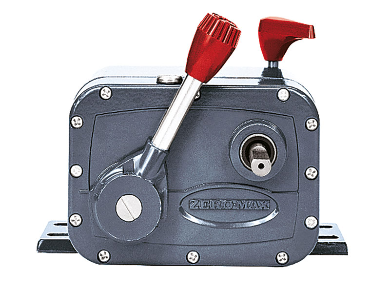
An adjustable zero-max drive is a mechanical gearbox that offers the option of infinitely variable adjustment of an input speed of up to 2000 rpm with a reduction ratio of 4:1. The speed is set via a lever or other optional control variants such as handwheel or fine adjustment. The Zero-Max adjustable speed drives can be categorized into unidirectional and reversible drives. Unidirectional drives have a defined and preferred input and output shaft direction of rotation. Reversible drives have a defined direction of rotation of the input shaft and offer the option of changing the direction of rotation of the output shaft. The output shaft of the reversible drives can be operated clockwise (CW), counterclockwise (CCW) and in neutral position. All Zero-Max standard drives are equipped with a hand lever control.
Functional principle:
The general functional principle of the adjustable drives can be traced back to the position of the four individual one-way couplings inside the housing. The position and distance between the individual components are changed by adjusting the hand lever. The number of strokes per coupling and minute is determined by the drive speed. Each coupling is moved forwards and backwards during one input shaft rotation, resulting in the corresponding stroke and pulse movements of the internal couplings per minute on the output shaft (output). If all four couplings operate at an input speed of 1800 rpm, the output shaft is actuated 7200 times per minute (1800 x 4) or 120 times per second (7200 : 60). If the input speed is reduced to 900 rpm, the shaft is still driven 3600 times per minute and the output speed is halved.
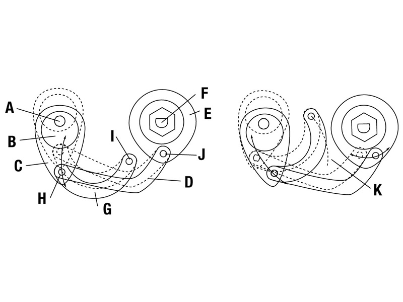
In the schematic diagram with shaft (A), camshaft (B) and connection rod (C), the rotary movement is converted into a linear movement. For the zero position, the main joint arm (D) swivels to positions (H) and (J) without moving the couplings. If the settings deviate from the zero position, the couplings (E) transfer the linear movement into the intended rotary movement and move the output shaft (F). The control joint (G) swings through the arc (K) as long as the control lever is moved.
A different output speed results at any position on the arc (K), as the direction in which the connecting rod swivels changes from the vertical position (Figure left: zero speed position) to the horizontal position (Figure right: maximum speed position), which changes the length of the strokes that the main control joints transmit to the overrunning couplings.
What are the advantages of an adjustable speed drive?
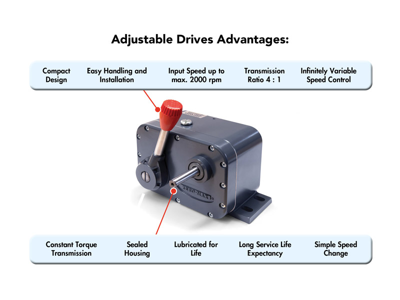
An adjustable speed drive offers a variety of advantages and possibilities that have developed over the years. For decades, the conditions and application requirements have been constantly changing to meet market demands. In line with the continuously increasing market requirements, significant product improvements have contributed to the success of adjustable speed drives. The following product features are therefore a fundamental part of this success:
- Robust product design with precise, infinitely variable speed regulation
- Five sizes available in torque range from 1.36 Nm to 22.6 Nm
- Transmission ratio 4 : 1
- Input speed up to max. 2000 rpm possible
- Output speed from 0-400 rpm
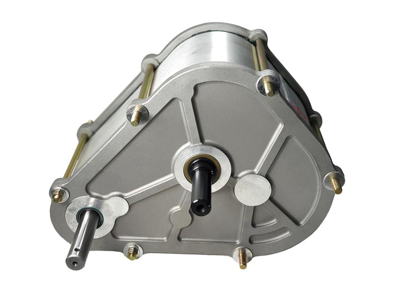
- Shaft arrangement freely selectable
- Long service life expectancy
- Ideal suitability for dancer control applications
- Compact design
- Easy handling and installation
- Factory lubrication
- Sealed housing
- Use under difficult ambient conditions
- Multiple mounting positions
- Versatile customization options (shaft, lever and motor)
In which applications can Zero-Max adjustable speed drives be used?
Adjustable speed drives can be provided as a main or secondary drive and offer the possibility of configuring different control options and shaft arrangements. Common applications or areas of use include:
- Textile machinery (looms, industrial sewing machines, braiding machines)
- Food processing (hamburger presses)
- Agricultural machinery (seed drill drives, grain dryers, seed equipment, agitators)
- Printing machines (high-speed cut-size sheeter for stacking finished sheets, ink pumps for the printing industry)
- Mechanical engineering (applications for tension control, dosing devices)
- Packaging machines (conveyor belts, rotary tables for filling)
What is the maximum output speed or the output speed range?
In general, all Zero-Max adjustable speed drives offer the option of infinitely variable adjustment of the output or output speed range from 0 to 1/4 of the input speed. There is a transmission ratio of 4 : 1 between input and output speed, or conversely 0.25 : 1 between output speed and input speed.
What product service life can I expect from my Zero-Max Drive?
The basic assumption for providing a service life expectation is the correct dimensioning and design for the application in consideration. With the correct product design, Zero-Max drives achieve an average service life of 15,000 to 20,000 hours. Important factors that must be considered when designing the adjustable speed drive and the expected service life include:
- Operating factor
- Start-stop characteristics (output/drive)
Slow and adjusted acceleration significantly extends the product service life.
- Shock loads and/or overload situations
Stresses caused by overload situations or shock loads should be avoided and lead to a reduction in the expected service life.
⇒ Recommendation: Install overload protection on the output of the Zero-Max drive
Is it possible to change the direction of rotation of the output shaft on a Zero-Max Drive?
In general, the functional principle is the same for all Zero-Max standard speed drives, the input shaft rotation is realized by one-way couplings and cannot be changed. The output shaft torque always remains constant over the entire speed range. Changing the input shaft direction of rotation does not therefore change the output shaft direction of rotation.
Zero-Max offers two models (E & JK series) with reversible output for a possible change in the direction of rotation. Both reversible series have a special coupling with a specific switching mechanism that enables the direction of rotation to be reversed.
Does the direction of rotation of the drive- or input shaft play a role?
The selection of the preferred drive shaft direction of rotation plays a crucial role in ensuring maximum service life expectancy. Operation against the direction of rotation preselection is possible, but can lead to vibrations, excessive noise and a reduction in service life at increased output shaft speeds.
Example of a preselection:
An overview of all recommended directions of rotation can be found on the homepage or in the corresponding data sheet.
Is heat emission during operation usual and can I repair a Zero-Max drive?
Occasionally, heat may be generated during operation of an adjustable speed drive, this can occur particularly during start-up and is not unusual. Once the run-in phase is finished, the heat emission is reduced and a further increase in temperature is not to be expected. All Zero-Max drives are extensively tested for leaks and faults in the test field before delivery. For further information, please refer to the relevant operating instructions. Zero-Max generally advises customers not to attempt repairs or maintenance on their own. If in doubt, please contact the relevant trade partner or contact Zero-Max directly.
How are adjustable speed drives lubricated?
All standard drives provided by the factory are lubricated for life. The sealed housing ensures that the oil level is optimally adjusted for all installation positions, guaranteeing lubrication for life. In the event of leakage situations during use, it is recommended that the oil supply does not exceed the centerline of the highest shaft. If more than the recommended amount of oil is filled in, this can lead to overpressure situations, which can negatively affect the performance of the device and the shaft seals. Corresponding recommendations can be found in the operating instructions.
Is there a recommended installation position?
In general, there is no recommended or mandatory installation position. Adjustable speed drives are usually mounted in a horizontal installation orientation using the mounting feet provided. Alternatively, other mounting arrangements are possible to fix the drive; wall mounting in a vertical installation situation or hanging upside down are no problem.
What customization options can be provided?
There are an endless number of possible customizations and modifications for Zero-Max adjustable speed drives across all sizes. The most common customizations or individual specifications are:
- Alternative lever designs
- Individual position of the control element
- Lever arm extensions
- Customized lever adaptations (bores, threads, splines, etc.)
- Pulsating output rotation (sewing machine puller wheel)
- One-cycle and two-cycle design (corresponds to one or two output pulses per input shaft rotation)
How many of the adjustable speed drives have been sold worldwide until now?
Zero-Max is proud to say that more than 1,000,000 adjustable speed drives are now in use worldwide, providing a cost-effective and robust product of the highest quality.
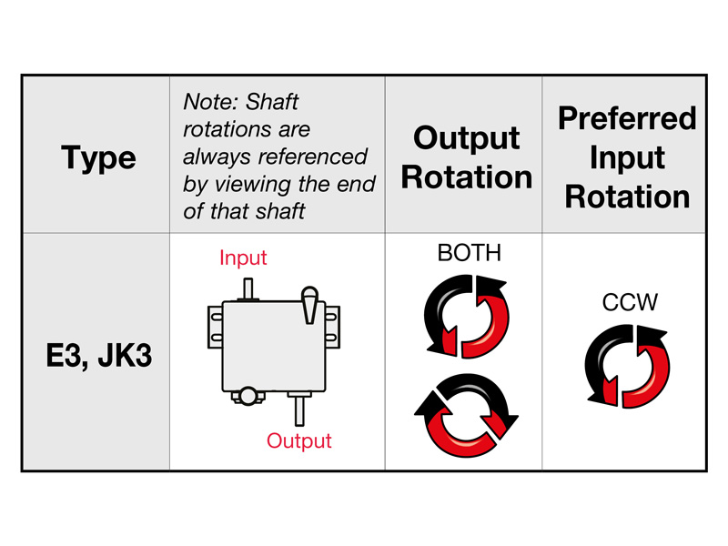
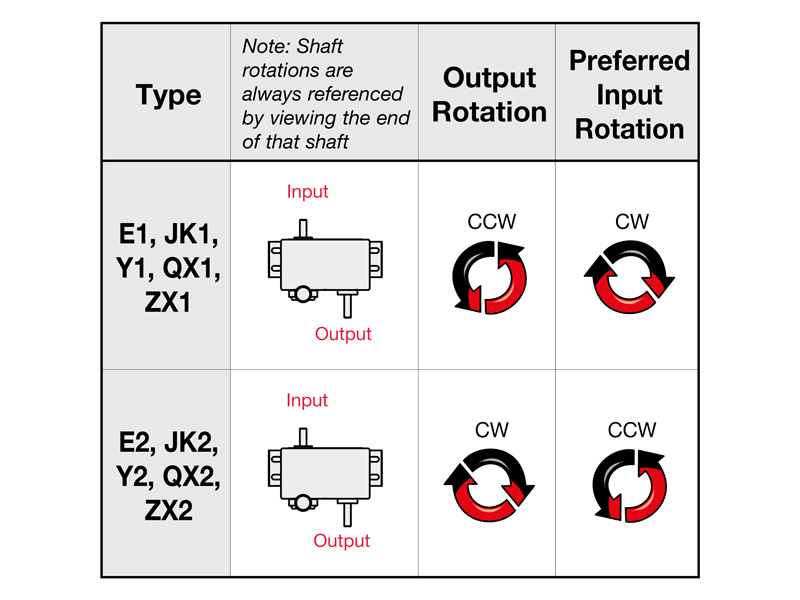
How is the correct direction of shaft rotation determined?
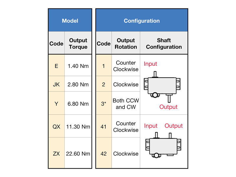
To correctly select the output shaft direction of rotation, it is important to define the input shaft direction of rotation as a fixed output variable. The output shaft direction of rotation is determined based on the specified input shaft direction of rotation. The output shaft direction of rotation is determined on the assumption that the view of the shaft end is decisive for the correct product configuration.
For example, selecting a configured drive with an output torque of 2.25 Nm and a preferred clockwise (CW) shaft rotation direction results in two possible designs. The drive model JK2 and JK42 can be selected, and the output shaft position is used to further narrow down the selection.
If the output shaft is opposite the input shaft, the JK2 series is selected. For a position next to the input shaft, a JK42 series is selected.
In general, the following codes result in the corresponding output shaft directions of rotation:
Code 1: corresponds to the counterclockwise (CCW) direction of rotation of the output shaft
Code 2: corresponds to the clockwise direction of rotation of the output shaft (CW)
Code 3: corresponds to a reversible direction of rotation (only available for the E-series and JK-series)
Optional control options, additional gear ratios and integrated electric motors can also be defined and configured.
The relevant information can be found in the data sheets.
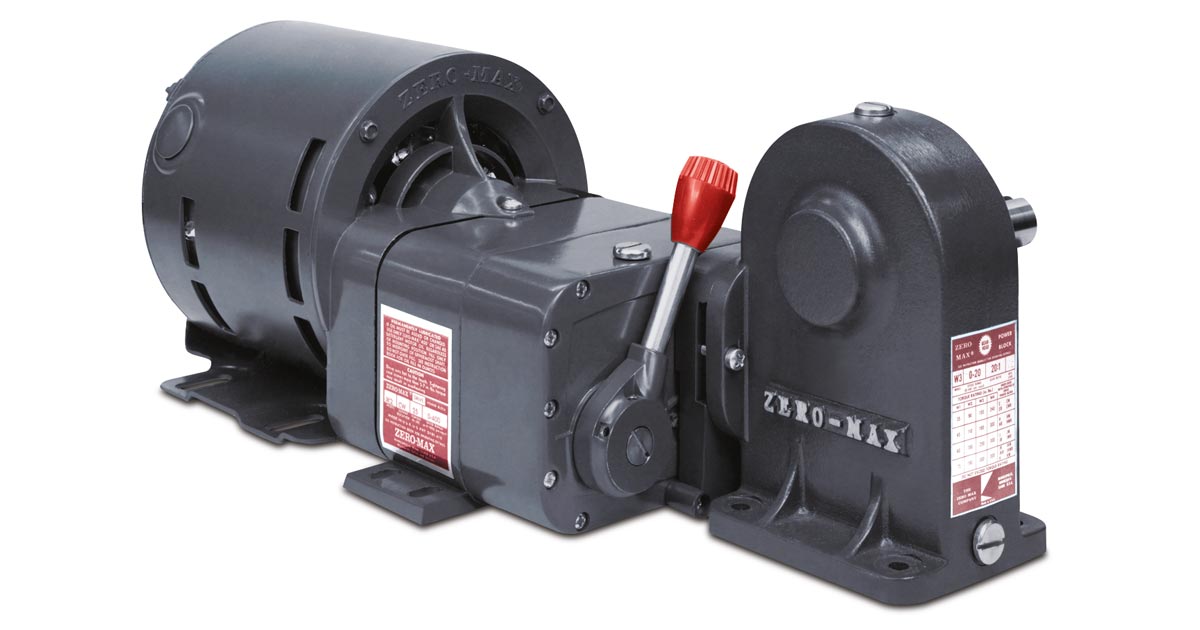
Are there options for connection to customer motors?
C-adapters can be integrated for the Y, QX and ZX series.
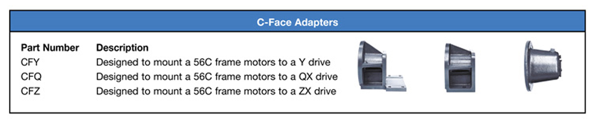
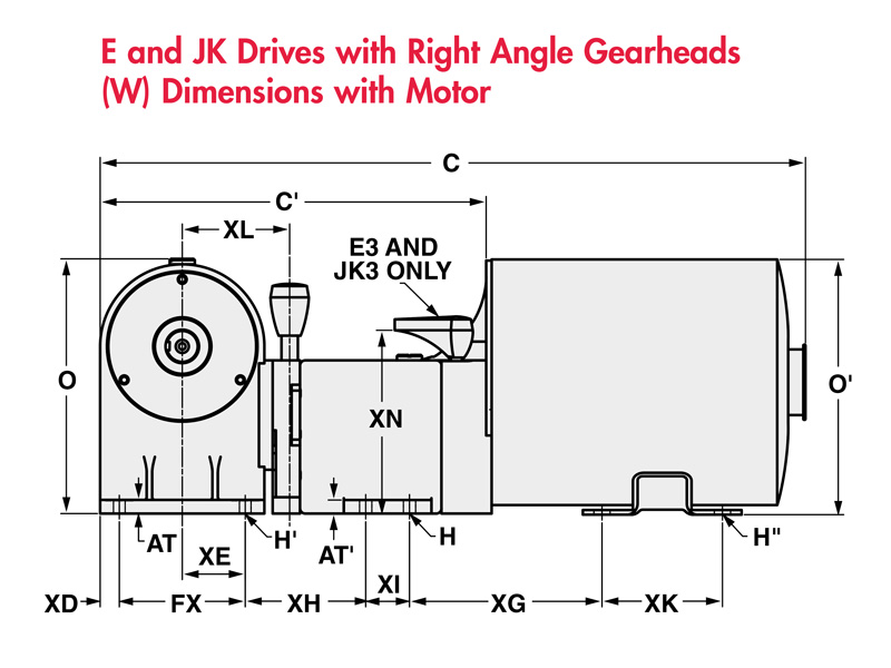
For the E & JK models, there is the option of an additional right-angle gearbox and an integrated electric motor.
Further technical data can be found in the data sheet.
Have we sparked your interest? Do you have any further questions? Then please do not hesitate to contact us.