Torq-Tender® & H-TLC
Reliable protection in case of overload
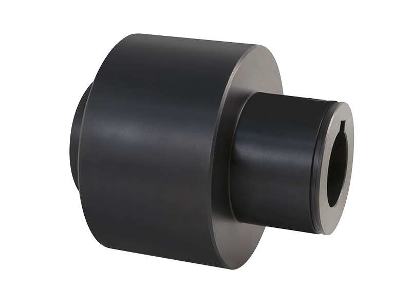
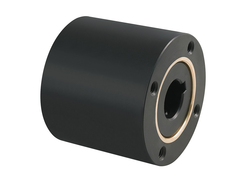
Torq-Tender
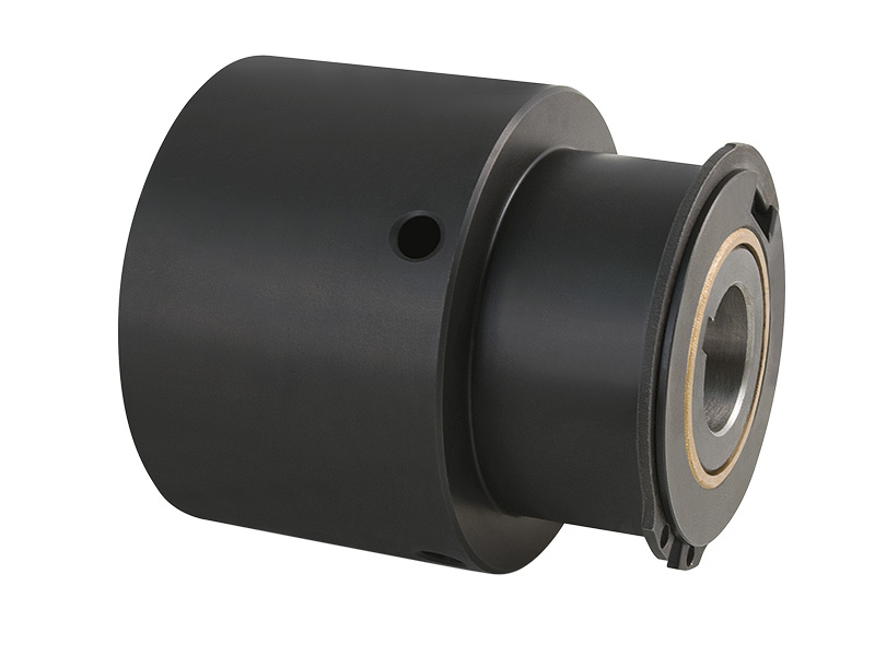
The Torq-Tender overload coupling is tamper-proof, i.e. the disengagement torque cannot be changed after installation. This product feature ensures smooth and safe operation. Costly and time-consuming calibration procedures are therefore superfluous. The desired release torque is defined during the ordering process, thus ensuring the correct spring set selection. In general, torque values can be adjusted by the user by replacing the spring assembly.
To adjust the torque range, the Torq-Tender overload coupling must be disassembled and fitted with the desired spring set. Standard Torq tenders work in a bidirectional direction, i.e. in the event of an overload situation, they disengage both clockwise (CW) and counterclockwise (CCW). The set disengagement or torque remains the same regardless of the direction of rotation. The Torq-Tender can be configured at the factory so that different disengagement torques are possible for different directions of rotation in the disengagement status.
In general, the Torq-Tender enables two functions when used as a coupling:
- Use as a flexible shaft coupling
- Mechanical torque limiter
In the “shaft-to-shaft” configuration, the Torq-Tender enables offsets of 1.5° and a parallel offset of 0.125 mm to 0.380 mm.
The closed design enables use in a wide range of industrial applications and environments. Customer-specific and individual product features can be adapted to the application requirements and enable use under the most adverse conditions.
If I use an electronic sensor, do I still need a mechanical safety coupling?
Electronic sensors are designed to detect excessive motor power due to increased torque load and shut down the motor accordingly. Often motors are positioned directly on the front driveline and are less sensitive to overload torques in the rear section of the motor due to torque multiplications from gear ratios and the overall inertia of the entire driveline. In addition, a motor can be used to drive several positions of a machine, making electronic sensors even less sensitive to overload situations in individual sections. A mechanical torque limiter such as a Torq-Tender benefits from precise and fast reaction times at any position in the drivetrain.
Where is the best place to install a Torq tender in my drivetrain?
Torq tenders should be installed in the immediate vicinity of the component needing protection in the drivetrain. An optimally selected positioning of the safety coupling enables fast disengagement times and protects the application from unforeseeable overload situations. The effects of gear reduction or inertial influences can thus be reduced.
Can each connection side of the Torq tender act as the drive or the driven connection side?
All standard Torq tender series are designed for bidirectional operation, i.e. the safety coupling can be rotated or disengaged in all directions of rotation. As a result, it is possible to use the respective installation end as a driving or driven option.
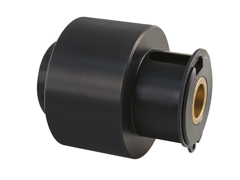
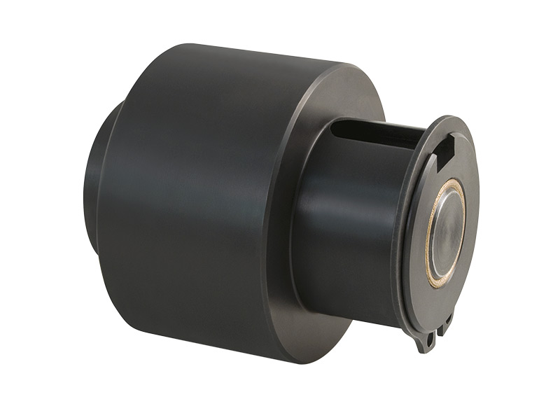
However, when using an actuating pin (model series CP, BP, SP, JFP, JP), it is important that the “housing” end of the Torq-Tender is connected to the drive side of the system. The actuating pin is positioned on the Torq-Tender to enable signaling at the limit switch or sensor system in the case of an overload situation. In the overload situation, the actuating pin is pushed radially out of the housing.
For models with an actuating disc (CD, BD, SD, JFD, JD series), each end can serve as the drive side, but make sure that the actuating disc is actuated in the direction of the limit switch or the sensor device in the system.
What can I do if my Torq tender disengages unintentionally?
Unexpected disengagement, especially during first time installations, often means that the torque setting for your machine is at the limit. Adjusting to the next highest torque spring setting for your Torq-Tender may be sufficient to eliminate the undesirable cause of the overload situation. The pre-defined release torque can be adjusted by replacing the integrated springs – see the Torq-Tender installation and replacement instructions for more details.
Other factors that may result in errors?
- Ensure that the Torq-Tender is in its engaged starting position before restarting the machine. If the actuating pin or the actuating disc is not in the reset starting position or engaged position, the machine inertia may prevent a reset in the restart. It is recommended to manually move the motor forwards or backwards to re-engage the Torq-Tender. Alternatively, it is possible to turn both sides of the safety coupling until the engagement position is reset. For both methods, an acoustic “click” should be heard to signal the re-engagement position.
- A “soft start” of the motor prevents an unexpected overload situation caused by excessive starting torque. Gradual acceleration reduces the starting torque and may help to rectify an overload situation.
- Unwanted overload or disengagement situations after long periods of use may indicate that the springs or the housing need to be replaced.
Is it possible to add an actuating pin or an actuating disc later?
The actuating pin can be ordered ex works for all Torq-Tender safety couplings. Torq tenders of sizes TT3 and larger can be supplied with an actuating pin on site. For sizes TT2X and smaller, modifications must be made at the factory. These product characteristics apply in the same way to all Torq tenders with an actuating disc.
How can I determine the torque setting for my Torq tender?
In the case that the torque setting is not provided in the machine manufacturer’s technical documentation, the torque range can be determined using the Zero-Max color coding. The setting range can be determined visually using the color-coded springs in the installed status. You can find corresponding instructions for identifying the installed springs and for identifying the springs by color code in our installation and spring replacement instructions.
Is it possible to adjust the disengagement torque “on field”?
The disengagement torque can be reduced or increased by replacing the installed springs. Instructions for replacing or adjusting the number of springs can be found in the installation and spring replacement instructions.
What is the maximum operating speed of the Torq-Tender torque limiter?
The Zero-Max Torq-Tender is designed for an operating speed of 1800 rpm. The performance of the Torq-Tender safety coupling may be affected in the higher speed range due to the inertia of the system. For applications with high operating speed requirements, please contact Zero-Max directly. Actuating pins and discs should be provided especially for high system requirements with high operating speeds. The use of actuating pins and discs enables immediate shutdown of the power transmission in the case of overload and thus prevents costly damage and failures.
Is the Zero-Max Torq-Tender backlash-free?
All Zero-Max torque tenders are subject to a rotational backlash of 1° – 1 ½°. This small amount of backlash is acceptable for most applications.
Is it possible to mount the Torq tender vertically or horizontally?
In general, it is also possible to mount the Torq-Tender in a vertical installation position. Please note that the vertically aligned shafts are fully supported in the installed bearings so that no additional axial thrust load is transferred to the Torq-Tender.
Which standard keyways or keyway connections are available?
All standard keyway sizes are based on AGMA (American Gear Manufacturing Association) and ISO standards. A corresponding overview and table of the standard keyway sizes can be found in the catalog for overload safety couplings in the “How to order” section. For individual keyway or spline profiles, please contact us directly and we will be happy to help you.
Is it possible to obtain Zero-Max torque tenders for cleaning applications (e.g. washdowns) or harsh environmental conditions?
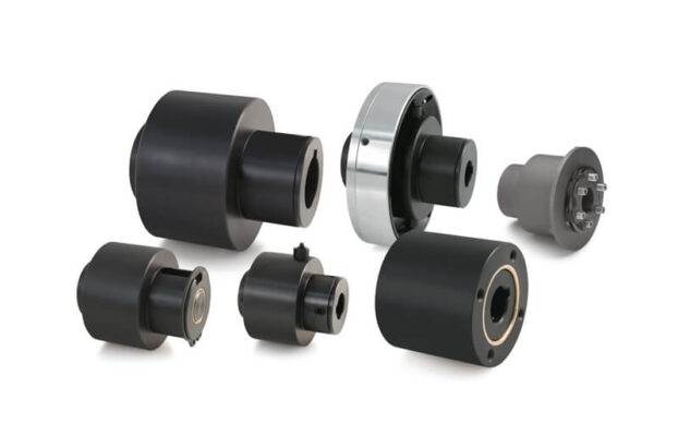
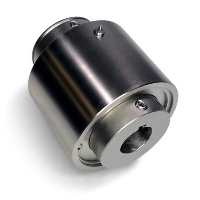
All standard versions of the safety coupling (TT) have a black oxide coating for light corrosion protection in industrial environments. Zero-Max offers further options for applications with high demands on the operating environment due to humidity, spray water or contamination. Coated or stainless product designs can be implemented according to customer requirements. The use of additional sealing components provides protection against contamination and water. Lubrication with food-safe grease is available as an option. For individual requirements, please contact us directly and we will be happy to advise you.
What happens if my Torq tender is operating in overload condition for a longer period?
The Zero-Max overload coupling (TT) is developed and designed for occasional and short-term release conditions. Repeated or continuous overload situations can lead to excessive wear of the components. Torque variations may occur as a result of the resulting wear of the components. Another result of excessive wear is a reduction in the release torque relative to the original torque setting. Ideally, an actuating pin or disc should be integrated for applications without monitoring or in the upper speed range. In the case of overload, the motor is switched off immediately by the use of safety couplings with optional actuating pins and discs and excessive wear is avoided. This system is often described with a freewheel behavior, i.e. implementation as a freewheel safety coupling would also be possible.
Is it possible to lock or block the Torq tender in one direction?
In addition to the standard models, Zero-Max can customize the disengagement torques with different settings in the CW and CCW directions. Another option is complete “blocking” in one direction.
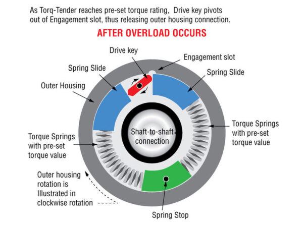
Functional principle Torq-Tender:
The unique product design of the TT enables the setting of individual disengagement points in CW and CCW direction. The blocking or locking characteristics can be implemented in the clockwise (CW) or counterclockwise (CCW) direction. The individual handling of the disengagement points also enables different disengagement torques in the respective directions of rotation (CW/CCW).
Can a Torq tender be implemented with different disengagement torques for the clockwise (CW) and counterclockwise (CCW) directions?
It is possible to set Torq tenders with different disengagement torques according to the direction of rotation, i.e. we offer the option of adapting this individually to customer requirements.
Application example using a TT1X-C:
For example, it would be possible for a TT1X-C with a setting range of 0.3 – 6.8 Nm to be set so that it triggers at 2 Nm in the clockwise direction (CW) and only triggers at 5 Nm in the counterclockwise direction (CCW).
Which optional adjustments are frequently implemented?
- Adaptation to the disengagement behavior
(freewheel couplings, one-sided and two-sided blocking behavior, different disengagement torques in clockwise and counterclockwise direction) - Customer-specific material selection
- Special sealing technology
- Customized coatings
- Use of food-grade lubricating grease
- Adaptation to customer-specific attachments
(sprockets, pulleys or other machine elements) - Customized bores and tolerances
In which applications and industries are torque tenders mainly used?
- Packaging machines
- Mechanical engineering
- Automation
- Speciality machinery
- Printing and converting machines
- Manual operation (e.g. handwheel operation)
Torq-Tender safety couplings provide safe protection when the specified disengagement torque is exceeded. In the event of an overload situation, the Torq-Tender quickly and reliably disconnects the power transmission, thus preventing system damage. Torq tenders are delivered from the factory with revision protection and impress with their bidirectional mode of operation.
- Nominal torque range up to 339 Nm
- Operating speeds up to 2000 rpm
- Temperature range from -40 °C to 93 °C
- Compensation of shaft misalignments
- Bore diameter up to ø48 mm possible
- Nickel-plated and stainless steel versions available
Do you have any questions? Get in touch with us!
H-TLC
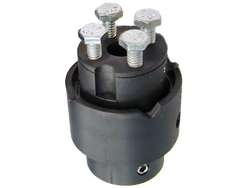
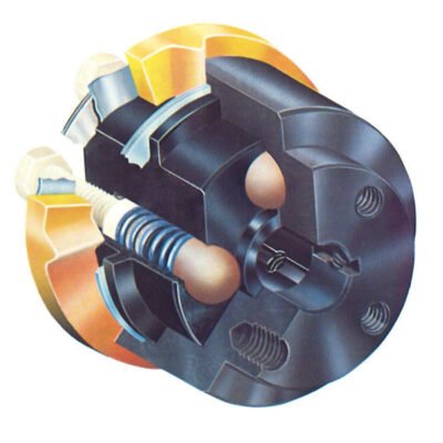
The Zero-Max H-TLC safety coupling was developed to handle overload situations and prevent machine failures. In the event of an overload, the power transmission is disconnected, preventing further excessive torque loads. The H-TLC torque limiter protects critical attachment components from unforeseen situations or events. The H-TLC has four (H-TLC 500) or six (H-TLC 1000) re-engagement points as standard, which is also referred to as disengagement behavior. Product versions with one switching point (synchronous latching behavior) are optionally available.
A unique feature of the H-TLC safety coupling is its use in difficult areas of application; this overload coupling can be operated completely submerged in oil. Other environmental influences such as water, salts and mild acids can also be mastered depending on the application. Another unique feature is the ability to define the position reset to one or two positions.
Can I manage without a mechanical torque limiter/safety coupling if I already have an electronic sensor in use?
Electronic sensors are designed to detect excessive motor power due to increased torque load and shut down the motor accordingly. Often motors are positioned directly on the front driveline and are less sensitive to overload torques in the rear section of the motor due to torque multiplications from gear ratios and the overall inertia of the entire driveline. In addition, a motor can drive several positions of a machine, making electronic sensors even less sensitive to overload situations in individual sections. A mechanical torque limiter such as an H-TLC benefits from precise and fast response times at any position in the drivetrain.
Where is the best place to install an H-TLC in my drivetrain?
H-TLCs should be installed in the immediate vicinity of the component to be protected in the drivetrain. An optimally selected positioning of the safety coupling enables fast disconnection times and protects the application from unforeseeable overload situations. The effects of gear reduction or inertial influences can thus be reduced.
Can each end of the H-TLC act as the drive or output end?
All standard H-TLCs are designed for bidirectional operation, i.e. the safety coupling can be rotated or disengaged in all directions of rotation. As a result, it is possible to use the respective installation side as a driving or driven option.
For models with an actuating disc, either end can be used as the drive side, but care should be taken to ensure that the actuating disc is actuated in the direction of the limit switch or the sensor device in the system.
What can I do if my H-TLC unintentionally disengages?
Unexpected tripping, especially during initial installations, often indicates that the torque setting is close to the limit required for your machine. Adjusting to the next highest torque spring setting for your H-TLC may be sufficient to eliminate the undesirable cause of the overload situation. The H-TLC can be set to the required disengagement torque by tightening the adjustment screws. If the desired torque setting cannot be achieved with the installed springs, the next larger spring assembly may have to be considered.
The corresponding instructions can be found here
Other factors that may lead to malfunctions?
- Ensure that the H-TLC is in its engaged starting position before restarting the machine. If the actuating disc is not in the reset starting position or engaged position, the machine inertia may prevent a reset during restart. It is recommended to move the motor forwards or backwards manually to re-engage the H-TLC. Alternatively, it is possible to turn both sides of the safety coupling until the engagement position is reset. For both procedures, an acoustic “click” should be heard to signal the re-engagement position.
- A “soft start” of the motor prevents an undesirable overload situation caused by excessive starting torque. Gradual acceleration reduces the starting torque and may help to rectify an overload situation.
- Unwanted overload or tripping situations after long periods of use may indicate that the springs or the housing need to be replaced.
Is it possible to add an actuating disc afterwards?
The H-TLC safety coupling can be configured with an actuating disc during the ordering process; it can also be replaced in the field. To replace it, you need the actuating disc together with a retaining ring and a wave spring; these components are available ex works.
How can I determine the torque setting for my H-TLC?
If the torque setting is not specified in the machine manufacturer’s technical documentation, the torque range can be determined using the Zero-Max color coding. The setting range can be determined visually using the color-coded springs in the installed state. You can find corresponding instructions for locating the installed springs and identifying the springs by color code in our installation and spring replacement instructions.
| Model | Blue Spring (Nm) | Red Spring (Nm) | Gold Spring (Nm) |
|---|---|---|---|
| 500 | 0.5–6.8 | 4.5–14.1 | 11.3–16.9 |
| 1000 | 4.5–16.9 | 15.8–39.5 | 33.9–56.5 |
What is the maximum operating speed of the H-TLC torque limiter?
The Zero-Max H-TLC is designed for an operating speed of 1800 rpm. The performance of the H-TLC safety coupling may be affected in the higher speed range due to the inertia of the system. For applications with high operating speed requirements, please contact Zero-Max directly. Optional actuating discs should be provided especially for high system requirements with high speeds. The use of actuating discs enables the power transmission to be interrupted immediately in the event of an overload, thus preventing costly damage and failures.
Is the Zero-Max H-TLC backlash-free?
All Zero-Max H-TLC´s are subject to a rotational backlash of 1°-2°. This small amount of play is acceptable for most applications.
Is it possible to mount the H-TLC vertically or horizontally?
In general, it is also possible to mount the H-TLC in a vertical installation position. Please note that the vertically aligned shafts are fully supported in the installed bearings so that no additional axial thrust load is transferred to the H-TLC.
Which standard keyways or keyway connections are available?
All standard keyway sizes are based on AGMA (American Gear Manufacturing Association) and ISO standards. A corresponding overview and table of the standard keyway sizes can be found in the catalog for overload safety clutches in the “How to order” section. For individual keyway or spline profiles, please contact us directly and we will be happy to help you.
Is it possible to obtain a Zero-Max H-TLC for cleaning applications (e.g. washdowns) or harsh environmental conditions?
All standard versions of the H-TLC safety coupling are corrosion-resistant. The product design is based on a housing body made of durable composite material with components made of coated steel and stainless steel. For additional corrosion protection, alternative concepts with additional stainless steel components or springs can be implemented. The use of food-safe lubrication is optional. Please contact us directly for further modifications.
What happens if my H-TLC is operated in overload mode for a longer period?
The Zero-Max overload coupling (H-TLC) is designed and engineered for occasional and short-term release conditions. Repeated or continuous overload situations can lead to excessive wear of the components. Torque deviations can occur because of the resulting wear of the components. Another result of excessive wear is a reduction in the release torque relative to the original torque setting. Ideally, an actuating disc should be integrated for applications without supervision or in the upper speed range. In the event of an overload, the motor is switched off immediately using safety couplings with optional actuating pins and discs and excessive wear is avoided.
Which areas and fields of application are suitable for the H-TLC?
In the past, applications in the field of packaging technology in particular have emerged as ideal areas of use. Feeding and timing screws in particular benefit from the use of H-TLC.
In this area, accelerating, decelerating, aligning, sorting and separating individual containers is an essential part of the process.
The H-TLC provides economical overload protection for unforeseen load situations and offers the “wash-down” feature. Food processing applications benefit from this product feature.
Possible applications:
- Feeding and separation of containers, jars
- Conveyor belts in washing processes
- Overhead conveyors for dry cleaning processes
- Applications with star wheels (separating, merging)
The unique and innovative torque limiter H-TLC is a perfect solution approach for applications with harsh environmental influences such as humidity, corrosion, acids and many other environmental influences. Simple and infinite torque adjustment coupled with precise and reliable operation make the H-TLC an ideal torque limiting solution. The components made of polymer materials enable smooth operation, even under the most adverse conditions. The materials used offer low weight and prevent waste heat during operation.
- Operating speeds up to 2000 rpm
- High chemical resistance, use in oil possible
- Nominal torque range 0.5 to 56.5 Nm
- Bore range from ø8 mm to ø30 mm
- Temperature range from -40 °C to 82 °C
- Compensation of shaft misalignments
If you have any further questions, please do not hesitate to contact us!
